18 May 2023
Building a retro gaming computer using logic gates


This week I had the pleasure of welcoming Richard Pawson to Fulford School in York and we had a really exciting conversation about helping GCSE and A Level Computer Science students build links between topics. It can be really hard to promote deep understanding when subject knowledge is separated into discrete sections of an exam board syllabus but the "how" and "why" questions of motivated students really make the job worthwhile and enjoyable.
We talked about light bulb moments of connecting the dots all the way between logic gates and the structure and function of a processor: how hard it can be for students to grasp how each part of a CPU is made up of NAND / AND / OR / NOT / XOR gates.
Richard very kindly donated a Gigatron to my students which is a kit to solder together a working microcontroller capable of playing retro games but made entirely of TTL ICs (no Raspberry Pi, arduino or other microcontroller in sight). I promised to try to document the process of soldering it together and exploring how all the parts work.
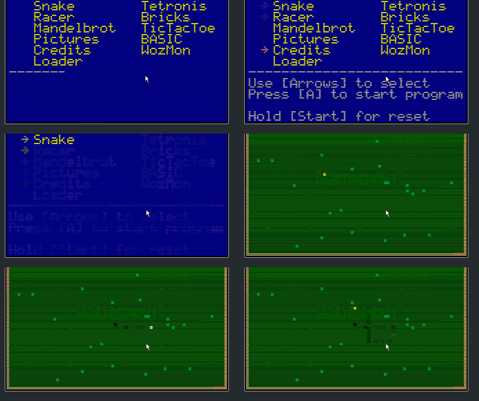
Gigatron kits were developed by Marcel van Kervinck and Walter Belgers as a simple(ish) 8 bit retro microcomputer made entirely out of 1970s era TTL integrated circuits. The finished version connects to a VGA display (no graphics card - the signals are all generated by software) and uses a game pad or keyboard to control some retro games. You can try out an simulated version here: https://gigatron.io/emu/
I run a Game Development Club on a Thursday after school with many students who create and play their own games. Today, I showed them the gigatron and asked for volunteers to help solder all the parts together.
I promised Richard that I'd attempt to write up the learning process of finding out how all the different parts of the computer worked in case any student or teacher would benefit from an introduction to the exciting crossover between electronics and computer science.
If you're interested in following that journey, I'll share it here: https://blog.withcode.uk/2023/05/how-do-computers-work-part-1-introduction/
If you have any questions, suggestions or comments - my students and I would love to hear your thoughts via the CAS discussion forum below.


Discussion
Please login to post a comment
Had a couple of my students playing around with “DIgital Logic Sim” (Digital Logic Sim by Sebastian Lague) and “Digital Logic Sim 2” Digital Logic Sim 2 by Lime Inc. … start with AND and NOT gates and ‘build’ other gates.
I think NandToTetris was an extremely worthy attempt, but I feel that its weak point is that all the exercises in low level logic circuit design are conducted in a textual hardware definition language (HDL) from the outset. Much better to work in a visual/spatial representation such as CircuitVerse (or many other interactive logic design simulations) until your circuits get to the point where they themselves can interpret a textual language (e.g. machine code) - then you move on.
This looks great - thank you.
This too - thanks for the links
If you have a bunch of questions about why it works, nand2tetris is fantastic.
Brilliant - thank you. I’ve already learnt a lot and I know I’ve got a lot more to learn!
My pleasure, Pete. I had bought the Gigatron kit with the intent of building it myself, but have finally admitted to myself that I have too many projects on the go, and I will gain more pleasure from seeing your students, under your able guidance, learn from it.
I would like to add, though, that I learned an enormous amount just from watching Walter Belgers’ 50 minute video about the design of the Gigatron, and studying the schematic diagrams and other documentation on their site. In particular:
RISC vs. CISC
Walter gives a very clear illustration of what RISC really means, in a way that most of the A-level textbooks don’t. The Gigatron has just 8 instructions (LoaD, STore, ADD, SUBtract, AND, OR, XOR, and Branch) - though with 4 addressing modes on many, and multiple conditionals (e.g. GT, LT, EQ) on the branch.
Each instruction takes exactly 1 clock cycle. On a CISC some instructions may take many clock cycles. More importantly, in that case you need ‘microcoding’ which may be thought of as a kind of interpreter for the machine code instructions - and the microcode for each instruction is written in an even lower level language than machine code! On a CISC microprocessor, the microcode occupies a large proportion of the ‘silicon real estate’. (For the Gigatron that would mean much more complex design and many more chips). On a RISC processor, the real estate freed up by no microcode is used for creating many registers, on-chip caching, and (for ARM) a ‘barrel shifter’. (A regular shift register - a line of flip-flops - can shift one bit per clock cycle. A ‘barrel’ shifter is a square array of flip flops, dynamically switchable, that can shift the register any number of bits in a single clock pulse!)
RISC means that a given piece of functionality will typically take more instructions to code than on a CISC. However:
Memory is now not the critical resource that it was in the early days of computing. Most computers now have more memory than you ever need.
Most machine code programs are no longer written or read by humans: they are almost all written by compilers, so needing to write more instructions for a given function does not involve more programmer effort, nor more opportunity for error.
Instruction decode
The instruction decoder on the Gigatron is just an array of diodes - very simple and elegant. The opcode (held in the Instruction Register) feeds into one side of the diode array, and each bit is or is not connected to one of the several output lines on an adjacent side of the array - and those output lines just activate switches on the ALU and various buses.
Harvard architecture
CAS readers may be aware that I believe most of what is said about Harvard Architecture (HA) in school (and university) textbooks to be complete nonsense. I wrote the only article on HA to have been published in a peer-reviewed journal - see The Myth of the Harvard Architecture. Nonetheless, the Gigatron is one of the few genuine examples of the so-called Harvard architecture (a term that dates back only to the 1970s, not to Howard Aiken’s Harvard Mk I), and their motivation for adopting this is very clear: it’s a simpler design. Improved speed, though automatic pipelining was (beneficial) side-effect - not the rationale. Moreover, it clearly shows the huge limitation of HA: it requires the program to be in ROM - which works for the Gigratron because all programs are written in BASIC and interpreted by a ROM based interpreter.
The ALU
What the Gigatron clearly shows is that the ALU (which connects directly to the Accumulator - as an input and/or as an output) consists of a bit-wise full Adder (which we teach our pupils) and what I call a ‘programmable logic unit’ or PLU (there doesn’t seem to be a standard term for this) which we don’t teach. I mentioned this (item 2) in this blog post. The PLU is a very simple circuit with 2 data input lines and 4 control lines, which can act like any logic gate (and is how the AND, OR, and XOR instructions work). Effectively you just put on the 4 control lines the final column of the truth table that you want!
Huge thankyou to @Richard_Pawson for coming and sharing his time and expertise this week and for donating a gigatron kit to me and my students. Limited progress so far, but really exciting to make a start!